Back

Grid Colors

    • 01 White
      01 White
    • 08 Black
      08 Black
    • 44 Satin Silver
      44 Satin Silver
    • Color-all
      Color-all
    • RAL
      RAL
Back

Product Performance

Load Bearing Expand to view deflection table
  Component Load Test Data and Material
Main Tee Length Allowable Load per ASTM C635
Hanger Spacing
    4' 5' 6'
Cross Tee Length 20" 2' 30" 3' 4'
200.XXZ.01 144"     HD 8.9 5.6
207.01H 60"          
209.01Z 48"         9.1
211.01Z 144"     ID 6.0 4.0
216.01H 120"     ID 6.3 3.9
229.01Z 24"   32.5​▲      
250.01Z 144"     ID 6.3 3.9
251.01H 12"          
252.01Z 24"   41.0​▲      
253.01H 36"       34.7  
254.01Z 48"         14.1
257.01Z 20" 90.0​▲​        
258.01H 30"     57.4    
270.XXZ.01 144"     HD 8.9 5.6
278.01H 96"          
299.01H 120"     ID 6.0 4.0

To convert data into lb/ft2, divide on center spacing of component into lb/ft.
▲ Limited by safety factor of 2.

  Light Fixture Load Test Data (based on 1/360 span deflection)
Dimensions Light Fixtures
Main & Cross Tees - Allowable Fixture Weight – Pounds
200.XXZ.01 207.01H 211.01Z 209.01Z 299.01H 207.01H 250.01Z 254.01Z 270.XXZ.01 254.01Z
1’ x 4’ 32.4 56.4   55.6 67.6
2’ x 2’ 29.2 34.8   49.6 52.8
2’ x 4’ 40.8 47.2   64.0▲ 76.0▲
2’ x 5’ 40.8        
3’ x 3’ 63.0▲        
20” x 48”     37.6    
20” x 60”     37.6    

Consult specific U.L. design for allowable lighting configurations.
▲ Limited by safety factor of 2.

Fire Rated Assemblies Hanger Positions for Fire Rated Situations
This illustrates hanger positions for single fixtures in a field and are covered in the table. Refer to specific design numbers for allowable number of fixtures per square footage of ceiling area.
Non-Fire Rated Assemblies Hanger Positions for Non-Fire Rated Situations
This illustrates hanger positions for single fixtures in a field. Provide extra hangers for tandem fixtures.
Environment Materials and Resources (MR)
-Waste Management Planning
-Interiors Life Cycle Impact Reduction
-Environmental Product Declarations
-Sourcing of Raw Materials
-Material Ingredients
-Waste Management
Indoor Environmental Quality (EQ)
-Low-Emitting Materials
-Interior Lighting
-Acoustic Performance
Back
  Component Load Test Data and Material
Main Tee Length Allowable Load per ASTM C635
Hanger Spacing
    4' 5' 6'
Cross Tee Length 20" 2' 30" 3' 4'
200.XXZ.01 144"     HD 8.9 5.6
207.01H 60"          
209.01Z 48"         9.1
211.01Z 144"     ID 6.0 4.0
216.01H 120"     ID 6.3 3.9
229.01Z 24"   32.5​▲      
250.01Z 144"     ID 6.3 3.9
251.01H 12"          
252.01Z 24"   41.0​▲      
253.01H 36"       34.7  
254.01Z 48"         14.1
257.01Z 20" 90.0​▲​        
258.01H 30"     57.4    
270.XXZ.01 144"     HD 8.9 5.6
278.01H 96"          
299.01H 120"     ID 6.0 4.0

To convert data into lb/ft2, divide on center spacing of component into lb/ft.
▲ Limited by safety factor of 2.

  Light Fixture Load Test Data (based on 1/360 span deflection)
Dimensions Light Fixtures
Main & Cross Tees - Allowable Fixture Weight – Pounds
200.XXZ.01 207.01H 211.01Z 209.01Z 299.01H 207.01H 250.01Z 254.01Z 270.XXZ.01 254.01Z
1’ x 4’ 32.4 56.4   55.6 67.6
2’ x 2’ 29.2 34.8   49.6 52.8
2’ x 4’ 40.8 47.2   64.0▲ 76.0▲
2’ x 5’ 40.8        
3’ x 3’ 63.0▲        
20” x 48”     37.6    
20” x 60”     37.6    

Consult specific U.L. design for allowable lighting configurations.
▲ Limited by safety factor of 2.

Back
Back
Back

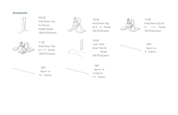
Accessories

148780_r1_ROC_GridDS_EPSFiles_SingleImages_200

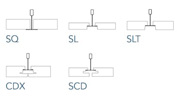
Compatible Tile Edge Types

1516-inch Edges

200/250 Systems

Back

Resources


print pdf
icon
Rockfon Seismic Relief Brochure

pdf
icon
Rockfon Seismic Relief Brochure FR

pdf
icon
EPD Steel CISCA
EPD Steel CISCA

pdf
icon
Chicago Metallic® 200 Hook-Grid™ 15/16" Exposed Datasheet

pdf
icon
Rockfon® Accessories Datasheets

pdf
icon
Rockfon® Accessories DataSheet FR

pdf
icon
Rockfon Seismic Perimeter Details: Tech Note

pdf
icon
Rockfon Fire Rated Ceiling Assemblies: Tech Note

pdf
icon
Rockfon Acoustical to Drywall Ceiling Transition Tech Note

pdf
icon
Rockfon Using 12 Gauge Hanger Wire Installation Guide

pdf
icon
Chicago Metallic® Standard 15/16" and 9/16" Exposed Grid Systems Installation Guide

pdf
icon
Chicago Metallic® Standard 15/16" and 9/16" Exposed Grid Systems Installation Guide FR

pdf
icon
Rockfon Using Grid Adapters Installation Guide

pdf
icon
Rockfon Product Cleaning and Maintenance Tech Note

pdf
icon
Rockfon Product Cleaning & Maintenance Tech Note FR

pdf
icon
Chicago Metallic 200 Hook Grid 15-16 Exposed Specification

pdf
icon
Chicago Metallic 250 Fire Front Hook Grid 15-16 Specification

pdf
icon
Chicago Metallic 200 Hook Grid 15-16 Exposed CDN Specification

pdf
icon
Chicago Metallic 250 Fire Front Hook Grid 15-16 CDN Specification

pdf
icon
Rockfon 40 Year Suspension System Warranty

pdf
icon
Sample Order Form: Chicago Metallic 200

Click 'PDF' to download and customize your grid system sample kit.

pdf
Back